Language


Views: 225 Author: Yuhang Power Publish Time: 2026-10-25 Origin: Site
Content Menu
● Drone Motor vs Underwater Thruster: Key Differences
● Why Water Changes the Propulsion Requirements
>> Fluid Loading Changes the Motor's Operating Point
>> Propeller Geometry Must Match the Medium
● Waterproof Drone Motor vs Underwater Thruster: What Protection Really Means
>> Weather Resistance Is Not a Submerged Operating Specification
>> Flooded Construction Can Be Intentional
>> Depth Creates Additional Failure Paths
● KV, Torque, Cooling, and Control: Why Matching Voltage Is Not Enough
>> KV Does Not Measure Underwater Suitability
>> Cooling and Lubrication Must Be Designed Together
>> The Controller Must Support the Mission
● Why Headline Thrust Can Mislead
● How to Compare Underwater Thrusters Without Misreading the Data
>> Use a Consistent Test Basis
>> Do Not Confuse Static Thrust With Vehicle Efficiency
● A Practical Validation Plan for OEM and ODM Projects
● Can a Drone Motor Be Converted Into an Underwater Thruster?
>> 1. Can a Brushless Drone Motor Run Underwater?
>> 2. Is a Waterproof Drone Motor Suitable for Saltwater?
>> 3. Can an Underwater Thruster Run in Air?
>> 4. Can I Use the Same Controller for Both Systems?
>> 5. Does Higher KV Mean More Underwater Thrust?
A drone motor and an underwater thruster may both use brushless motor technology, but they are designed for fundamentally different operating environments. In a drone motor vs underwater thruster comparison, the important differences extend beyond waterproofing. Fluid loading, propeller geometry, bearing lubrication, cooling, corrosion protection, and control behavior all affect whether the propulsion system works reliably.
For equipment developers, the practical question is not whether a motor can spin underwater. It is whether the complete assembly can deliver predictable thrust throughout its intended service life.
My starting point when evaluating either system is simple: match the complete propulsion system to the operating environment, rather than selecting a motor by appearance, voltage, or advertised power alone.
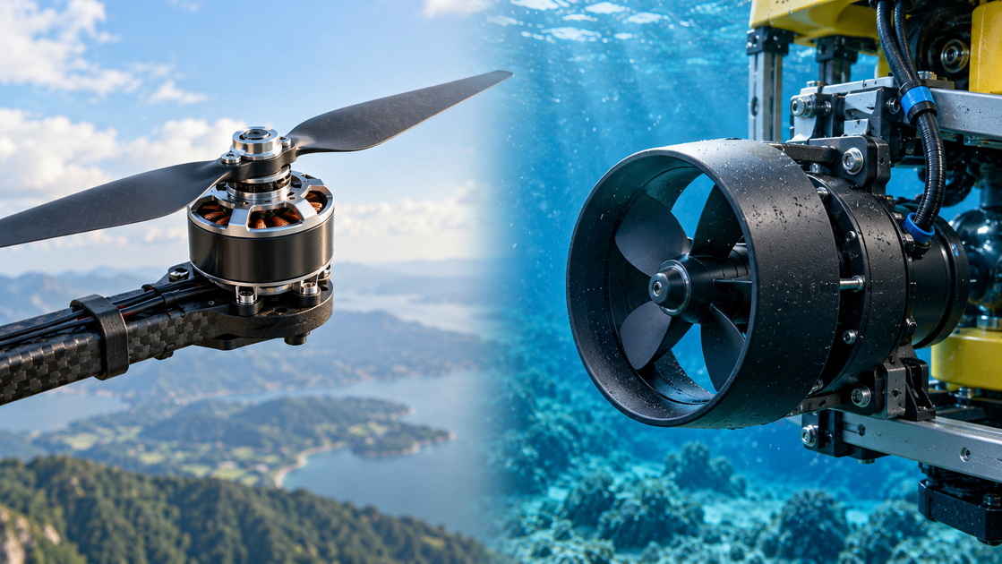
First, distinguish the components. A drone motor is an electric motor, usually specified separately from its propeller and electronic speed controller. An underwater thruster is normally a propulsion assembly incorporating a motor, marine propeller, mounting structure, and sometimes a protective nozzle.
A fair comparison therefore considers the complete motor–propeller–controller combination.
| Comparison Point | Typical Drone Propulsion System | Typical Underwater Thruster |
|---|---|---|
| Operating medium | Air | Freshwater or seawater |
| Primary design priorities | Low mass, flight efficiency, responsive thrust | Submerged reliability, controlled thrust, environmental durability |
| Propeller design | Aerodynamic blades matched to flight conditions | Hydrodynamic blades matched to underwater loading |
| Environmental protection | Varies from exposed construction to weather-resistant designs | Components engineered for the specified submerged environment |
| Bearings | Commonly grease-lubricated rolling bearings | May use water-lubricated bushings or protected bearings |
| Cooling | Commonly relies on airflow | May use surrounding water or a designed internal thermal path |
| Direction control | Often optimized for one operating direction | Frequently requires controlled forward and reverse thrust |
| Validation | Airborne thrust, temperature, vibration, flight duty | Submerged thrust, pressure, corrosion, leakage, and endurance |
These are typical patterns, not universal rules. Specialized products can differ substantially.
A propeller produces thrust by accelerating fluid. The force depends on how much fluid passes through the propeller and how much its velocity changes.
Water places a very different load on a rotating propeller than air. For a defined propeller and operating condition, thrust and torque depend on fluid density, rotational speed, diameter, and performance coefficients.
This does not mean an aerial propeller produces a predictable multiple of its airborne thrust when submerged. Its operating point changes, and the motor may be unable to maintain the intended speed.
An unsuitable combination can experience:
- Excessive current draw.
- Poor startup or stalled rotation.
- Overheated windings or controller electronics.
- Blade deformation or mechanical failure.
- Unstable thrust and vibration.
The engineering problem is a load mismatch, not simply a lack of waterproof coating.
Drone propellers are developed around aerodynamic loading, weight, stiffness, and flight performance. Underwater propellers must satisfy hydrodynamic requirements and withstand their intended submerged loads.
Diameter, pitch, blade area, thickness, and tip clearance all matter. A nozzle can influence thrust and protect the propeller, but it does not automatically make every design more efficient.
For buyers, the useful specification is a measured performance curve for the actual propeller assembly—not a motor rating combined with an unrelated propeller.
"Waterproof" is often used broadly in product descriptions. It should never replace a precise statement of operating conditions.
A motor suitable for rain exposure is not automatically suitable for continuous immersion, seawater, or operation at depth. Ask what the protection claim covers:
- Splashing, temporary immersion, or continuous submerged operation?
- Freshwater or saltwater?
- A stationary product or a rotating assembly?
- What depth, duration, temperature, and inspection criteria?
A protective coating may help isolate electrical components. It does not, by itself, establish bearing suitability, connector integrity, shaft sealing, or pressure resistance.
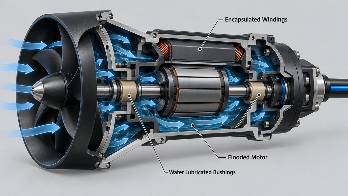
Some underwater brushless motors deliberately allow water into the motor assembly. Their windings are electrically encapsulated, while exposed components use materials and protection appropriate to the environment.
Other designs keep the motor dry inside a sealed housing or use a pressure-compensated arrangement.
Neither approach is universally superior. Flooded designs require suitable electrical isolation and wet-running components. Sealed designs require dependable housings, seals, and thermal management.
The critical question is whether the entire architecture has been validated for the application.
Ocean pressure increases by approximately one atmosphere for every 10 meters of depth, in addition to atmospheric pressure at the surface.
Pressure can affect housings, seals, cable penetrations, trapped air spaces, and connectors. A successful shallow-tank demonstration therefore does not establish deepwater capability.
Request documented pressure-test conditions for the complete assembly, including its cable entry—not just a depth claim for the motor body.
Motor KV describes the approximate relationship between rotational speed and applied voltage under no-load conditions. It is not a thrust rating or a measure of environmental durability.
A low-KV drone motor is not automatically an underwater motor. Likewise, there is no universal KV threshold separating aerial and marine propulsion.
Evaluate KV alongside winding resistance, torque demand, current limits, cooling, propeller geometry, and duty cycle.
An aerial motor may depend on propeller-driven airflow. Submerging it changes heat transfer, but does not automatically make the complete assembly thermally safe.
A marine motor may benefit from direct water cooling, yet still experience local overheating if encapsulation, loading, or internal heat paths are poorly matched.
Bearing requirements also differ. Some underwater thrusters use water-lubricated plastic bushings that depend on immersion during operation. Extended dry running can damage these components.
Follow the specific manufacturer's instructions. A dry-running limit published for one thruster must not be treated as a universal allowance.
Underwater positioning often requires repeated transitions through neutral, smooth low-speed response, and reverse operation.
Some aerial controllers support bidirectional operation, but that does not establish suitability for a particular thruster. Verify:
- Reliable startup under the actual propeller load.
- Forward and reverse command behavior.
- Neutral deadband and calibration.
- Current limits and thermal protection.
- Cable-length effects and installation requirements.
- Safe response to lost control signals.
Reverse rotation also does not guarantee equal thrust in both directions.
The published Blue Robotics T200 specification lists 5.25 kgf forward thrust and 4.1 kgf reverse thrust at a nominal 16 V. Full-throttle forward input power at that voltage is listed as 390 W.
The useful lesson is not that every project needs this particular product. It is that one assembly can have materially different forward and reverse capabilities.
For an inspection robot, that difference may influence braking, station keeping, and recovery maneuvers. Designers should use directional performance data rather than assume symmetric behavior.
Also distinguish kilograms-force from kilograms of mass. A thrust figure does not state how much vehicle payload a system can carry underwater. Buoyancy, drag, vehicle orientation, and thruster placement affect the result.
This published example is a reference point, not a performance claim for Zhongshan Yuhang Power Technology Co., Ltd.
Two impressive thrust figures may describe different operating conditions. Before comparing suppliers, request the following information:
| Required Information | Why It Matters |
|---|---|
| Voltage measured at the controller | Battery labels can conceal voltage sag |
| Current and electrical input power | Establishes the electrical load |
| Forward and reverse thrust curves | Reveals directional capability |
| Propeller and nozzle configuration | Confirms which assembly produced the results |
| Water conditions and test arrangement | Helps identify inconsistent comparisons |
| Test duration and temperature history | Separates brief output from sustained operation |
| Continuous operating limits | Supports realistic mission planning |
Compare performance near the expected operating point. A vehicle that spends most of its mission holding position may benefit more from controllable low-output performance than maximum thrust.
Static thrust testing is useful, but it measures performance under a particular test condition.
Vehicle motion, nearby structures, inlet restrictions, and recirculating flow can change installed performance. A favorable thrust-per-watt figure in a test tank is not a complete prediction of endurance.
A sound purchasing decision combines component curves with installation testing.
For a new underwater robot, I would use the following sequence before approving production hardware.
1. Define the mission: operating depth, water type, vehicle speed, current conditions, duty cycle, and expected service life.
2. Specify the complete propulsion package: motor, propeller, controller, cables, connectors, mounts, and protective structures.
3. Review environmental evidence: pressure tests, material compatibility, electrical isolation, and stated operating limits.
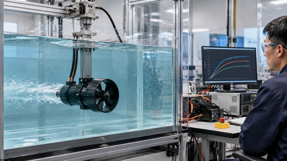
4. Measure submerged performance: forward and reverse thrust, input power, startup behavior, temperature, and vibration.
5. Repeat testing in the installed geometry: confirm clearance, inlet access, cable routing, and control response.
6. Inspect after endurance testing: look for coating damage, corrosion, loosened hardware, bearing wear, and electrical degradation.
Use guarded fixtures and appropriate electrical protection. Keep hands, loose clothing, and unsecured cables away from rotating propellers.
This process turns an attractive sample into a documented engineering decision.
In principle, a brushless motor can form the basis of a custom underwater propulsion system. In practice, conversion may require substantial redesign.
Potential changes include winding encapsulation, rotor protection, bearing replacement, compatible fasteners, cable termination, a different propeller, and controller retuning.
The assembly then needs thermal, endurance, pressure, and corrosion validation appropriate to its mission. Applying resin to exposed windings is not equivalent to completing that work.
Conversion can make sense for research or a specialized development program. For commercial equipment, compare the total development and validation cost against a purpose-designed thruster.
The reverse substitution is also problematic. An underwater thruster may depend on water lubrication, carry unnecessary airborne mass, and use a propeller poorly matched to flight.
Some can rotate underwater briefly, but rotation does not establish reliability. Electrical isolation, bearings, corrosion protection, propeller loading, and controller behavior must all be suitable for submerged operation.
Not necessarily. Confirm explicit saltwater operating conditions, material compatibility, cable protection, and maintenance instructions. Weather resistance alone does not demonstrate saltwater durability.
Only within its manufacturer's stated limits. Water-lubricated bearings may suffer damage during dry running, and the thermal conditions differ from submerged operation.
Possibly, if voltage, current, startup behavior, control protocol, and directional operation are compatible. Validate the actual motor–propeller combination rather than relying on the controller's current rating alone.
No. KV alone cannot predict thrust. Propeller geometry, loaded speed, torque, input power, and thermal limits determine the usable operating range.
1. NASA Glenn Research Center. "Propeller Thrust." Explains thrust through mass flow, fluid density, swept area, and velocity change. [Read the technical explanation]. [www1.grc.nasa]
2. International Towing Tank Conference. "Recommended Procedures and Guidelines: Model Manufacture—Propeller." Defines propeller advance ratio and thrust coefficient, including the relationship between thrust, fluid density, rotational speed, and diameter. [Read the technical document]. [ittc]
3. NOAA National Ocean Service. "How Does Pressure Change with Ocean Depth?" Provides the approximate pressure increase per 10.06 meters of seawater depth. [Read the explanation]. [oceanservice.noaa]
4. Blue Robotics. "T200 Thruster." Provides product-specific forward and reverse thrust, electrical specifications, construction details, and dry-running precautions. Numerical examples in this article refer to this manufacturer's published specifications, not Yuhang products. [View the product specifications]. [bluerobotics]
5. Blue Robotics. "Thruster User Guide." Covers operation, water-lubricated bearings, dry-running restrictions, and practical handling guidance. [Read the user guide]. [bluerobotics]
6. Blue Robotics. "M200 Motor for USVs, AUVs, and Subsea Applications." Describes flooded brushless construction, encapsulated stators, corrosion protection, water cooling, and water-lubricated bushings. [View the construction details]. [bluerobotics]
7. Blue Robotics. "Technical Reference." Explains underwater brushless motors and bidirectional electronic speed controller operation. [Read the technical reference]. [bluerobotics]
8. T-Motor. "U8 II KV150 Multi-Rotor UAV Motor." Illustrates why aerial motor protection claims should be evaluated against their stated rating rather than interpreted as continuous underwater capability. [View the product information]. [store.tmotor]


