Language


Views: 232 Author: Yuhang Power Publish Time: 2026-08-30 Origin: Site


Content Menu
● What Is FPV Motor Winding Resistance?
● Why Winding Resistance Matters in FPV Systems
● Tools for Accurate Brushless Motor Testing
● Safety and Preparation Before Testing
● How to Test FPV Motor Phase Resistance
>> Method 1: Milliohm meter or four-wire test
>> Method 2: Voltage-drop test with a current-limited supply
● How to Check for Open Circuits and Ground Faults
>> Check winding-to-frame insulation
● Reading the Results: A Practical Fault Table
● Expert Troubleshooting After a Crash or Overheat
● When to Replace, Rewind, or Request Engineering Support
● Build a More Reliable Motor System
>> 1. What is a normal FPV motor winding resistance?
>> 2. Can I test an FPV motor with a normal multimeter?
>> 3. Should all three motor phase readings be identical?
>> 4. Can I measure winding resistance with the motor connected to the ESC?
>> 5. Why does my FPV motor measure higher when hot?
FPV drone motor winding resistance testing is one of the fastest ways to identify a damaged phase, partial short, broken winding, or frame fault before it causes an ESC failure or an in-flight loss of power. For low-resistance FPV brushless motors, however, a basic multimeter can be misleading—accurate diagnosis depends on correct isolation, temperature control, lead compensation, and phase-to-phase comparison.
At YAHREE, we work with brushless motor applications ranging from FPV drones and RC vehicles to high-speed blowers, gimbals, underwater robots, cleaning robots, and OEM power systems. In engineering support and post-crash troubleshooting, winding resistance is a useful first electrical health check—but it must be performed and interpreted correctly.
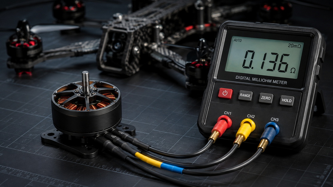
Motor winding resistance is the electrical resistance of the copper wire coils inside a brushless motor stator. In a three-phase FPV drone motor, each phase winding contributes to the magnetic field that drives the rotor.
Winding resistance is affected by:
- Copper wire length
- Wire diameter and cross-sectional area
- Number of winding turns
- Winding pattern and termination method
- Copper temperature
- Solder joints, motor leads, and connector condition
- Partial shorts, damaged insulation, corrosion, or broken conductors
Resistance itself does not determine motor quality. A low-resistance motor may support high current, but it can also generate very high heat if the propeller, battery, ESC settings, or airflow are unsuitable. What matters during troubleshooting is whether the three phase readings are balanced, repeatable, and consistent with the motor's documented baseline or specification.
For FPV motors, phase resistance is often in the milliohm range. That means the resistance of ordinary meter probes can be similar to—or even higher than—the motor measurement itself. A conventional multimeter that only resolves 0.1 Ω may be useful for detecting a complete open circuit or a major short, but it is often not precise enough to confirm a subtle phase imbalance.
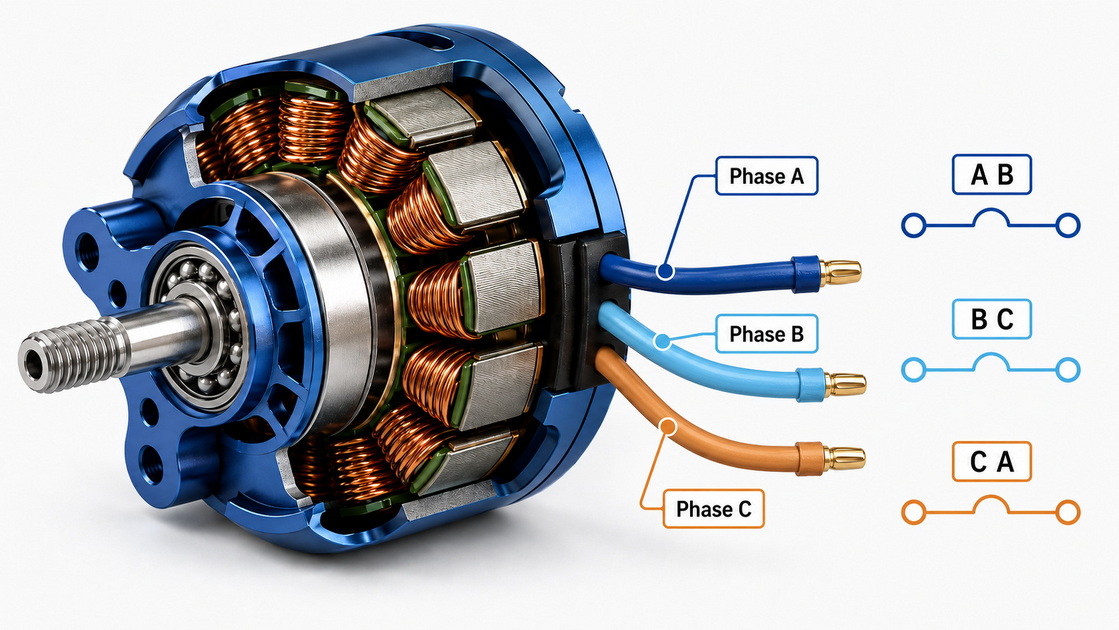
A brushless motor, ESC, battery, propeller, and flight controller operate as one power system. When one motor phase becomes electrically abnormal, the ESC may be forced to deliver uneven current. The result can be reduced thrust, excessive heat, desync, rough startup, abnormal sound, or ESC MOSFET damage.
A phase that measures unusually high may indicate:
- A partially broken winding conductor
- A damaged solder joint between wire and motor lead
- Corroded or strained motor wires
- Heat-damaged copper or terminal connections
- An intermittent connection revealed by bending the lead
Higher resistance raises copper loss, calculated as:
Pcopper loss=I2R
Even a small increase in resistance can become important when current is high. In an aggressive FPV setup, current increases quickly during punch-outs, prop wash recovery, and sustained full-throttle flight.
A phase pair with unusually low resistance may indicate:
- Turn-to-turn insulation damage
- Partial internal short
- Melted enamel coating on magnet wire
- Conductive debris, moisture, or contamination
- A direct short between phase wires
A partial short can be especially dangerous because a motor may still spin on the bench. Under load, it can draw abnormal current, overheat rapidly, and transfer stress to the ESC.
For a healthy three-phase motor, readings between A–B, B–C, and C–A should be closely matched. A difference beyond the motor manufacturer's tolerance—or a stable difference of roughly 5% or more in a controlled measurement—is a reason to investigate. Precision low-resistance measurement is important because lead resistance and probe contact can otherwise create false differences. Four-wire Kelvin measurement removes lead resistance from the result and is widely used for precise winding resistance work.
The right tool depends on the motor size and the diagnostic goal.
| Tool | Best use | Key limitation |
|---|---|---|
| Standard digital multimeter | Finding open circuits, direct shorts, and obvious faults | Often lacks milliohm resolution for FPV motors |
| Milliohm meter | Comparing FPV motor phase resistance | Quality and probe contact still matter |
| Four-wire micro-ohmmeter | Production, QA, engineering, and high-accuracy comparison | Higher cost and more setup |
| Bench power supply + DMM | Voltage-drop measurement with known current | Requires current limiting and careful setup |
| Insulation resistance tester | Checking winding-to-frame insulation in suitable motors | Do not apply high test voltage without confirming motor/ESC compatibility |
| Motor datasheet or baseline record | Final comparison and acceptance decision | Generic online values are not a substitute |
For a manufacturing environment, OEM validation program, or recurring service workflow, a four-wire Kelvin micro-ohmmeter is the preferred option. It sends test current through one pair of leads and measures voltage with separate sense leads, so cable and contact resistance are not included in the reported value.
For field work on a small FPV motor, a milliohm-capable meter or constant-current voltage-drop test is usually more informative than a general-purpose 0.1 Ω multimeter.
Never test a motor while it remains connected to an ESC, battery, flight controller, or powered test stand. The ESC's MOSFET circuitry can distort readings and may be damaged by inappropriate test methods.
Before beginning:
1. Disconnect the battery completely.
2. Disconnect all three motor wires from the ESC.
3. Remove the propeller before any powered testing.
4. Let the motor cool to a stable ambient temperature.
5. Inspect the motor wires, solder joints, and connectors for cut insulation, discoloration, loose strands, or corrosion.
6. Write down motor model, KV, stator size, test temperature, meter model, and readings.
7. Zero or compensate the meter leads before measuring low resistance.
Temperature must be controlled because copper resistance changes with temperature. For copper windings, resistance rises approximately 0.393% for every 1°C increase. This is why two measurements taken on a hot motor and a cool motor should not be compared without recording temperature.
A useful engineering approximation is:
RT2=RT1×(234.5+T2)/(234.5+T1)
Where R is resistance and T is winding temperature in °C. Use it as a comparison aid, not as a substitute for motor-specific quality criteria.
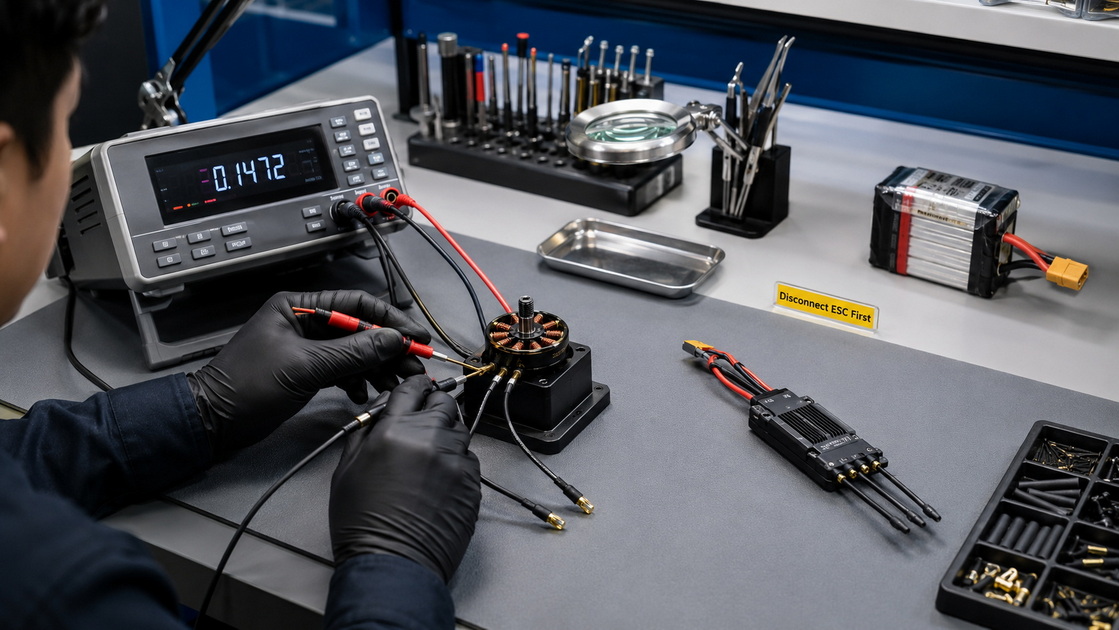
This is the most reliable method for FPV motors with very low phase resistance.
1. Isolate the motor from the ESC and all electronics.
2. Set the instrument to its lowest appropriate resistance range.
3. Compensate the leads according to the instrument instructions.
4. Measure phase pair A–B.
5. Measure phase pair B–C.
6. Measure phase pair C–A.
7. Repeat the full sequence at least twice.
8. Record the average reading and test temperature.
9. Compare the three results with one another and with the motor's baseline or specification.
Example: If A–B = 42 mΩ, B–C = 43 mΩ, and C–A = 42 mΩ under the same test conditions, the set is well balanced. If A–B = 42 mΩ, B–C = 43 mΩ, and C–A = 55 mΩ, further investigation is warranted.
Do not rely on a single measurement. Reposition probes and repeat. If the abnormal result moves when probe pressure changes, the issue may be measurement contact rather than an internal winding defect.
If you do not have a milliohm meter, use a known current and measure millivolts across each phase pair.
1. Connect a current-limited bench supply across phase A–B.
2. Use a stable low test current suitable for the motor and test setup.
3. Measure the voltage drop directly at the motor leads.
4. Calculate resistance using R=V/I.
5. Repeat for B–C and C–A.
6. Keep test duration short to avoid heating the winding.
7. Compare the three results at the same current and temperature.
For example, if 1.000 A produces a 45 mV drop, then the measured resistance is:
R=0.045V/1.000A=0.045Ω
A constant-current voltage-drop approach is a practical way to resolve low winding resistance when an ordinary DMM cannot.
An open circuit means current cannot pass through part of the winding. It may come from a broken magnet wire, failed solder joint, damaged motor lead, or severe thermal damage.
Measure A–B, B–C, and C–A:
- Healthy motor: All three values are low and similar.
- Open circuit: One or more pairs show "OL," infinite resistance, or a dramatically higher value.
- Intermittent open: Readings change when the wire is flexed gently near the solder joint or motor exit.
If the motor wiring is removable, test the motor-side pads separately from the extension cable. This isolates the source of the fault.
A basic multimeter check can identify an obvious direct short to the motor bell or stator housing.
1. Put one probe on a motor phase wire.
2. Place the other probe on clean, bare metal of the motor housing.
3. Repeat for each phase.
A healthy motor should show no conductive path to the housing on a conventional continuity or resistance check. A finite, repeatable low-resistance reading may indicate contamination, damaged insulation, or an internal fault.
For industrial insulation-resistance testing, a megohmmeter applies DC test voltage and measures insulation resistance between the winding and ground. This is not the same as a normal multimeter resistance test. Standard IR procedures also account for temperature and test duration.
Do not automatically use a high-voltage megger on compact FPV motors, integrated electronics, or connected ESC systems. Confirm the motor manufacturer's recommended method and test voltage first.
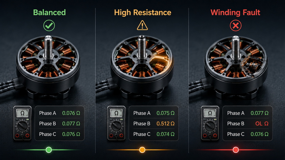
| Test result | Likely interpretation | Recommended action |
|---|---|---|
| A–B, B–C, and C–A are balanced | Windings are likely electrically healthy | Record results as a baseline |
| One pair is consistently higher | Partial open, poor solder joint, damaged lead, or heat damage | Inspect wiring and joints; retest |
| One pair is consistently lower | Possible turn-to-turn or phase short | Remove from demanding service and investigate |
| Any pair reads OL | Broken conductor or open winding | Repair lead/joint if external; otherwise replace or rewind |
| Any pair reads near zero unexpectedly | Direct short or measurement setup error | Verify with compensated leads; stop use if confirmed |
| Phase-to-housing continuity exists | Possible ground fault or contamination | Clean, inspect, and remove from service if persistent |
| Motor passes resistance test but runs hot | Mechanical, propeller, ESC, timing, or airflow issue may remain | Check the full propulsion system |
Winding resistance is a screening test, not a complete motor health certificate. A motor can have balanced resistance yet still suffer from bearing wear, bent shaft, damaged magnets, stator rub, poor dynamic balance, or load-related overheating.
When a pilot reports a burnt smell, hot motor, desync, unusual vibration, or one motor drawing more current, start with a repeatable sequence instead of replacing parts at random:
1. Inspect mechanically. Rotate the bell by hand. Feel for rough bearings, rubbing, shaft damage, loose bell screws, or debris.
2. Inspect electrically. Check the three phase readings and phase-to-frame isolation.
3. Swap components strategically. Move the motor to another ESC output only after confirming safe wiring. If the problem follows the motor, the motor is suspect; if it stays with the ESC output, inspect the ESC and solder joints.
4. Check the propeller. A bent, damaged, oversized, or incorrectly mounted prop can overload a healthy motor.
5. Review flight conditions. Repeated high-throttle operation, poor cooling, high ambient temperature, aggressive timing, or excessive filter-related oscillation can increase motor temperature.
6. Document results. Build a failure record with photos, resistance readings, temperature, propeller model, battery voltage, ESC firmware, and flight conditions.
For OEM and ODM projects, this documentation turns individual field failures into actionable design data. It can reveal whether the problem is related to winding specification, wire routing, connector choice, cooling, propeller load, assembly consistency, or ESC matching.
Replace or professionally rewind the motor when you confirm an open winding, a persistent low-resistance imbalance, insulation failure, severely heat-damaged windings, or a repeated thermal event with no external cause.
For commercial drone fleets, robotics platforms, RC product brands, and custom equipment, it is often more efficient to establish an incoming and outgoing quality-control process:
- Define a resistance baseline and permitted phase-balance tolerance.
- Test at a controlled reference temperature.
- Use four-wire measurement for low-resistance motors.
- Track serial or batch numbers.
- Combine electrical testing with no-load current, vibration, sound, and thermal checks.
- Review failures with the motor supplier before changing a design.
YAHREE supports brushless motor development and supply for FPV drones, UAV platforms, RC vehicles, blowers, gimbals, underwater systems, and other professional equipment. If your project needs a custom KV, stator configuration, winding specification, cable length, connector, mounting pattern, or complete propulsion-system matching, our engineering team can help define a testable specification from prototype through production.
Testing FPV drone motor winding resistance helps detect electrical damage before it becomes a costly failure. The most reliable workflow is simple: isolate the motor, measure all three phase pairs with suitable milliohm-level accuracy, record temperature, compare against a baseline, and investigate every persistent imbalance.
Need a custom brushless motor or complete power-system solution for an FPV drone, UAV, RC vehicle, blower, gimbal, underwater robot, or other high-performance product? Contact YAHREE to discuss OEM/ODM motor development, samples, technical specifications, and production support.
There is no universal normal value. Small high-KV FPV motors often have very low phase resistance, commonly in the approximate 0.02–0.2 Ω range, depending on size, KV, winding, and measurement method. The correct benchmark is the motor manufacturer's datasheet or a baseline recorded when the motor was new.
Yes, but mainly for obvious faults such as a complete open circuit, a direct short, or a clear housing short. Many FPV motor readings are too low for a standard meter with 0.1 Ω resolution to distinguish accurately. A milliohm meter, four-wire instrument, or voltage-drop test is better for phase comparison.
They should be very close under the same test conditions. Small measurement variation can come from probe pressure, lead resistance, and temperature. A stable difference of roughly 5% or more should trigger retesting and inspection rather than being ignored.
No. Disconnect all three motor wires from the ESC first. A connected ESC can create inaccurate readings and may be damaged by inappropriate testing methods.
Copper resistance increases as temperature rises. This is normal to a point. The important question is whether all phases rise similarly and whether the motor's temperature is appropriate for its application, propeller load, ESC settings, and cooling conditions.
1. [YAHREE, "Motor Winding Resistance — How to Test It."] Original article reviewed and expanded for this guide. [yrdrone]
2. [DV Power, "Motor Winding Resistance Test Procedure."] Reference for four-wire Kelvin measurement and the voltage/current resistance principle. [dv-power]
3. [Baldor-Reliance, "RPM Insulation Systems Evaluation and Maintenance Guidelines."] Reference for insulation-resistance testing concepts and correction to a common temperature. [baldor]
4. [Electrical Apparatus Service Association, "Performing an Insulation Resistance Test."] Reference for ground-insulation testing principles, instrument selection, discharge, and temperature correction. [easa]
5. [Electrom Instruments, "Winding Resistance Measurement Summary."] Reference for low-resistance measurement and the accuracy benefit of four-lead testing. [electrominst]
6. [UAV Model, "FPV Motor Winding Diagnosis: Detecting Burnt Phases, Shorts and Resistance Imbalance."] Reference for FPV-scale milliohm measurement and constant-current voltage-drop examples. [blog.uavmodel]


